Advanced triggering options
Triggering basics
Without triggering, the SmartScope would render each acquisition of a simple sine wave at a different timelocation. At ~150 acquisitions per second, this would make the sine wave appear all over the place. What you need, is the ability to define a certain voltage, and tell the SmartScope to position this voltage always at the same location on the screen. This is called triggering, and will result in a stable waveform on the screen.
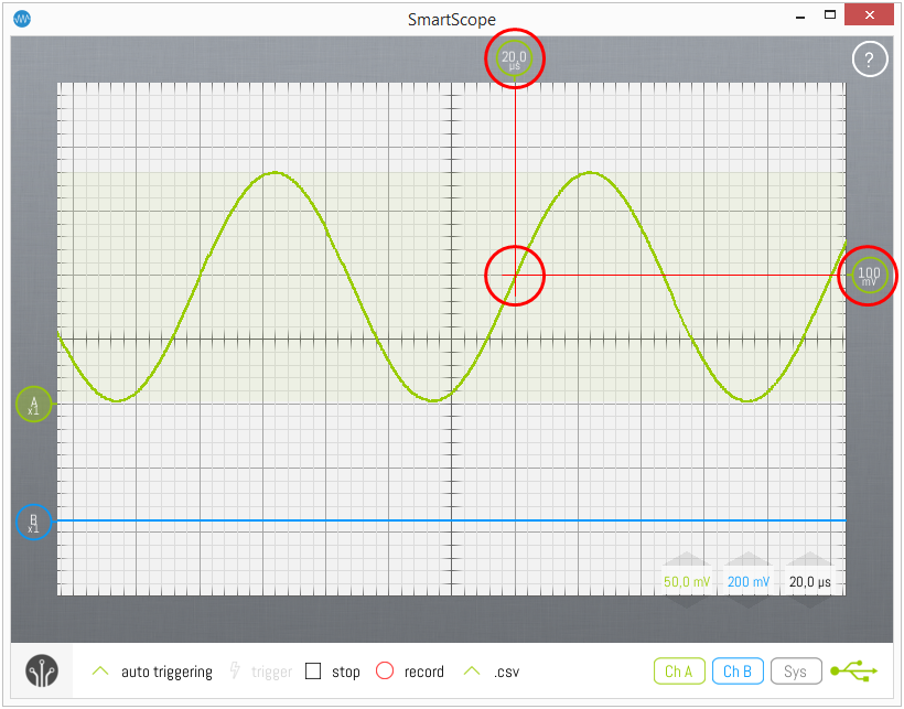
Trigger indicators
As shown in the image above, the voltage of this crossover point is defined by the Vertical Trigger Indicator on the right side of the screen. Simply drag it up/down to change the trigger voltage. Double-tap the indicator to reset the voltage to 0.00V. Additionally, you can also set the timelocation where you want the crossover point to be rendered. This is indicated by the Horizontal Trigger Indicator at the top of the screen. Simply drag this indicator, or any part of the main viewport, to the left/right to change the trigger location. Double-tap this indicator to reset the trigger position to 0s.
Trigger modes
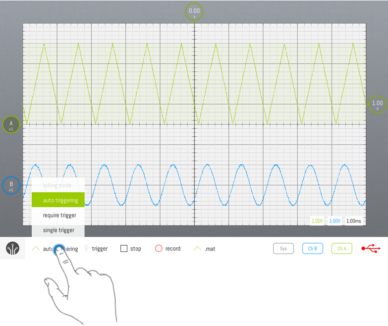
By default, the SmartScope will start using Auto triggering mode, and will switch to Rolling mode whenever you zoom the timebase beyond 20ms/div, to visualize slow signals. However, you can freely select the trigger mode of your choice by tapping on the Trigger type drop-up list, as shown below.
Notice that the ‘Rolling mode’ is only available when you’re visualizing slow signals (more than than 20ms/div).
Auto mode
In Auto mode, every time a trigger is detected, the waveform is acquired, transferred to the host and visualized. Whenever the trigger is lost (eg: when the input signal is removed, or when the signal changes so no more crossings with the trigger level occur), the SmartScope sends any acquired waveform to the host for visualization
Normal mode
In Normal mode, every time a trigger is detected, the waveform is acquired, transferred to the host and visualized, much like Auto mode. However, in case no trigger is detected, no new data is transferred nor visualized, keeping the last triggered waveform on the screen.
Single mode
Single mode puts the SmartScope in waiting mode until a trigger is detected. In such case, the waveform is acquired and visualized, after which the SmartScope puts itself in Stopped mode. Single mode is useful in case you want to visualize the very first occurrence of a trigger, or in case you want to capture a unique event and don’t want to remove the result in case of some glitch occurs when you remove the probe.
Rolling mode
When you’re visualizing slow signals, you end up with timebase settings like 100ms/div. With 10 divisions, this means it takes 1 seconds before an acquitisition can be made, so you only get screen refreshes every second. In such case, it is usually preferred to visualize the data as a continuously incoming stream of data, as you get realtime updates of the signal and you can stop the SmartScope whenever you want. This is what Rolling mode does.
The Trigger Menu is opened by tapping the Horizontal Trigger Indicator at the right of the screen:
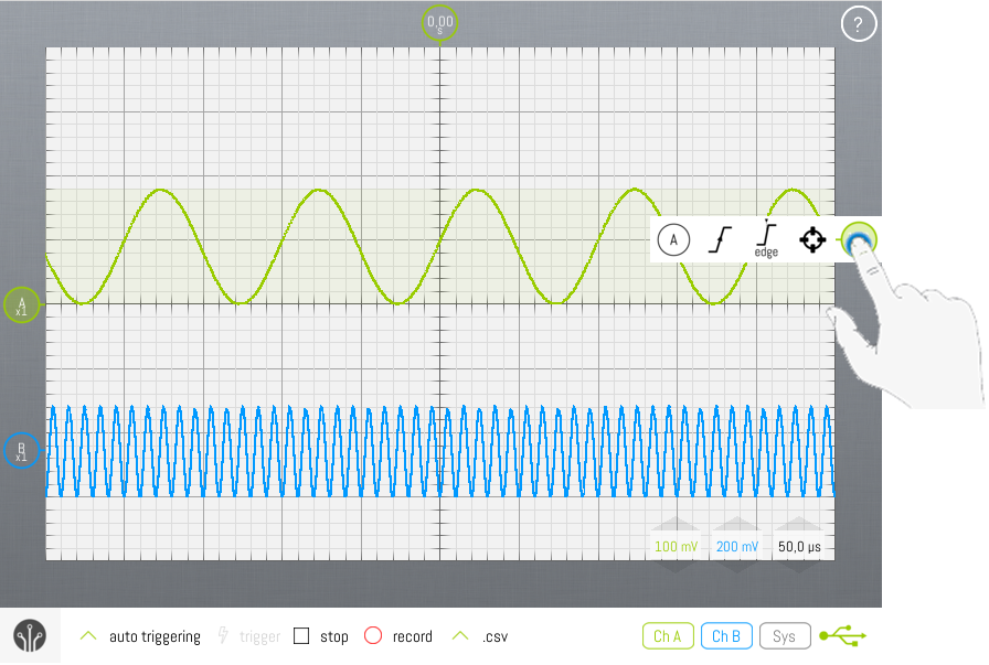
This will allow you to set (from left to right):
- Which channel to trigger on
- Which edge to trigger on
- The currently selected Trigger Type
- (any optional settings depending on the selected Trigger Type)
- The crosshair which will reset the trigger voltage to 0.00V
Changing trigger channel
You can specify which channel to trigger on, by opening the Trigger context menu as shown above, and tapping on the leftmost item. This will display a list of channels on which you can trigger. Changing trigger channel can also be done by hitting the T key when a keyboard is available.
Trigger Types
Edge triggering
The simplest of the three, Edge triggering simply waits for an edge to appear in your signal, and renders that acquisition to your screen. For a Rising edge, this means the position where the voltage transitions from below to above the Trigger voltage. Through the context menu, you can select whether the SmartScope should be waiting for a Rising edge, Falling edge, or whether Any edge will do.
Timeout triggering
In certain cases, you only want to look at signals which have been above (or below) the Trigger voltage for a certain amount of time. This can be useful to trigger on noise signals, or to detect periods of (in)activity. In order to select Timeout triggering, simply select it from the Trigger menu:
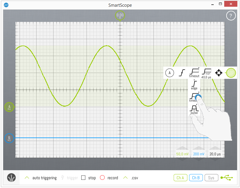
To define the Timeout period, tap on the Length button in the Trigger menu, after which a numpad will show up, allowing you to define your period of choice.
Please note the triggering position is NOT the moment of the edge, but rather the moment of the edge + the Timeout period, as can be seen in the Timeout icon. This is demonstrated in the image above, where you can see the positive edge is 40us before the Trigger location.
Pulse triggering
In other cases, you might be interested in pulses of a certain length. For these cases, the SmartScope supports Pulse triggering. In order to select Pulse triggering, simply select it from the Trigger menu:
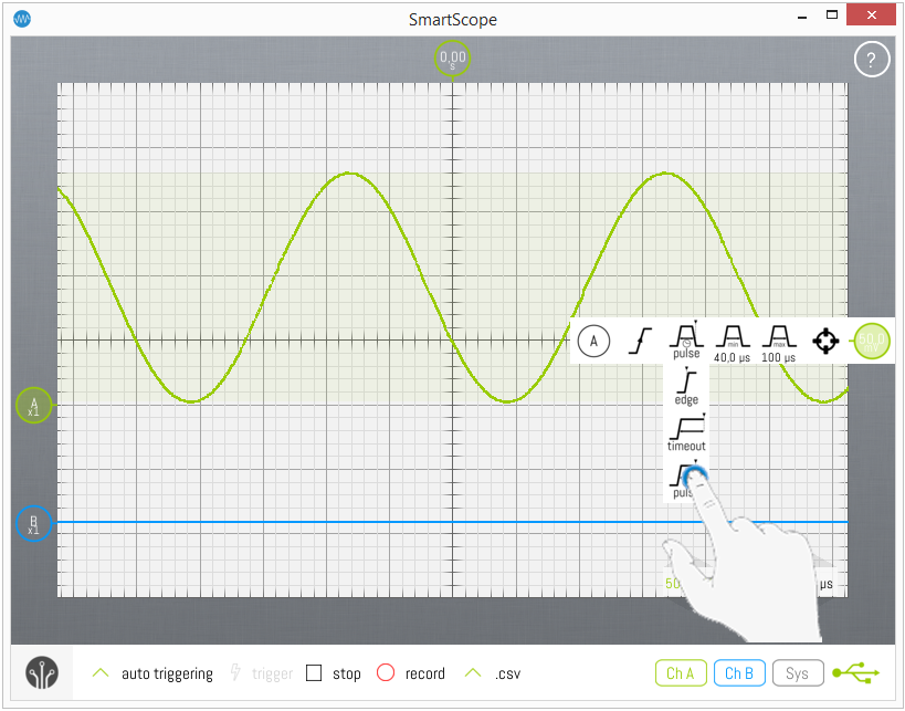
In Pulse triggering mode, you can specify a Minimum and Maximum length. Only pulses within these boundaries will cause the SmartScope to trigger. To set these Minimum and Maximum values, simply tap on them in the Trigger menu after which a numpad will be shown.
Please note the triggering position is NOT the moment of the edge, but rather the moment of the end of the pulse, as can be seen in the Pulse icon. This is demonstrated in the image above, where you can see the Trigger location is at the end of the pulse; ie where the voltage drops below the Trigger voltage again.