Creating your own Protocol Decoder: Difference between revisions
mNo edit summary |
JamesNewton (talk | contribs) (No mention was made of the development environment.) |
||
| (One intermediate revision by one other user not shown) | |||
| Line 1: | Line 1: | ||
The decoder framework has been created from the ground up with extensibility in mind. In case you want to use your own decoder in the SmartScope app, simply follow these steps (details info further down): | The decoder framework has been created from the ground up with extensibility in mind. In case you want to use your own decoder in the SmartScope app, simply follow these steps (details info further down): | ||
* Install and learn to use [http://www.visualstudio.com Microsoft Visual Studio] | |||
* Download the Decoder source package containing the sample decoder project | * Download the Decoder source package containing the sample decoder project | ||
*Copy an existing decoder file | *Copy an existing decoder file | ||
*Change the metadata, like Name and RequiredInputWaveforms | *Change the metadata, like Name and RequiredInputWaveforms | ||
* Code the logic of your decoder in the | * Code the logic of your decoder in the Process method | ||
* Compile the project | * Compile the project | ||
* Copy the resulting .dll file into the same folder as the SmartScope app | * Copy the resulting .dll file into the same folder as the SmartScope app | ||
Latest revision as of 17:13, 8 December 2015
The decoder framework has been created from the ground up with extensibility in mind. In case you want to use your own decoder in the SmartScope app, simply follow these steps (details info further down):
- Install and learn to use Microsoft Visual Studio
- Download the Decoder source package containing the sample decoder project
- Copy an existing decoder file
- Change the metadata, like Name and RequiredInputWaveforms
- Code the logic of your decoder in the Process method
- Compile the project
- Copy the resulting .dll file into the same folder as the SmartScope app
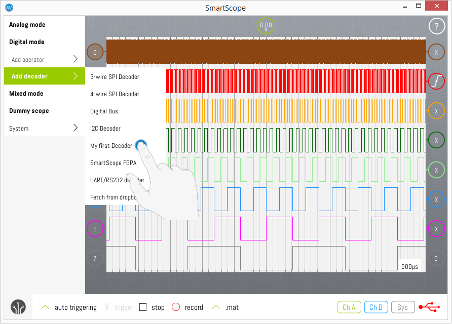
And voila, your custom decoder will show up nicely in the list of available processors!
Download the Decoder source package
Get the code from github - Some elementary instructions are available there as well
- Clone it to a local repo if you know how
- Otherwise, simply click the "Download ZIP" button on the right menu to download the full package as a .zip file
Next, run the Protobuild.exe program to create the solution files for your platform. In case of Windows, this will create (amongst other) the Decoders.Windows.sln file.
Start from an existing decoder file
Open up the Decoder project (windows: by double-clicking the Decoders.Windows.sln file).
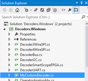
Next, click on the “DecoderI2C.cs” file in the Solution Explorer at the top-right of your screen. Hit Ctrl+C and Ctrl+V to duplicate that file. Select the resulting “DecoderI2C - Copy.cs” file, right-click -> Rename to give the file a meaningful name. In the example below, "MyCustomDecoder.cs" was chosen.
Double-click on the file to open up its contents. Change the original class name DecoderI2C to a name suiting your filename.
Define the metadata
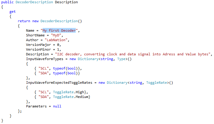
Time to focus on the code. Just underneath the class name, you’ll notice the Description which contains a couple of properties which define everything about your decoder the SmartScope app needs to know, except the decoding itself. Change all of them to suite your new decoder’s needs:

- Name: This is how your decoder will be presented by the SmartScope app in the list of available decoders.
- Abbreviation: Max 4 characters describing your decoder. These will be printed inside the indicator of your decoder wave at the very left of the SmartScope app.
- Author: Your name. Not used at the moment, sorry about that.
- VersionMajor & VersionMinor: In case multiple decoders with same name are detected, these field allow the SmartScope app to detect which instance it the most recent one.
- InputWaveformTypes: Here you define how many input waveforms your decoder requires, and which type of data they need to contain. This is done by using a Dictionary, linking the name of the wave to the type of required contents.
Optional:
- InputWaveformExpectedToggleRates: The SmartScope app contains functionality which allows to automatically map the correct input signal to the correct input of your Decoder. To allow this, you only need to specify which input sources you expect to toggle the most. This is done by a dictionary, specifying the expected ToggleRate for each input waveform.
- Parameters: Allows the user to specify additional paramteres, such as ActiveLow/ActiveHigh, or values such as Baud rates etc. See the DecoderUART for an example on this.
- ContextMenuOrder: Allows you to specify the order in which the InputWaves and Parameters will be presented in the Context menu of the SmartScope app. See the OperatorAnalogMath for an example on this.
Code your logic
With all preparations done, it’s time to focus on the fun stuff. Head to the Process method, which has 3 arguments:
- inputWaveforms: this is a list of arrays, containing all waveforms you specified above in the RequiredInputWaveforms property.
- parameters: this is a dictionary containing all paramters you specified above in the RequiredInputWaveforms property.
- samplePeriod: in case your decoder requires absolute timestamps, this argument is for you. By multiplying this value by the indices of your input arrays, you can find the exact time between them. In case your decoder would require 2 digital waveform and 1 waveform containing voltages (floats), you should have this:
NOTE: if you specify bool, the SmartScope app will pick up all logic channels and analog channels (the app will convert them to binary values for you). If you specify float, the SmartScope app will pick up analog channels only. In case you want to build a decoder which consumes the output of another decoder, you can also specify DecoderOutput as input type.
Now you’ll notice the inputWaveforms is a Dictionary, providing a typeless Array for each input you require. Before you can use the actual values inside the Arrays, you’ll want to cast them to Arrays containing the type your defined earlier. In case of our previous example, this is how this would be done:
Decoder output
Now you can go ahead and implement your decoder. The output of your decoder must be an array of DecoderOutput elements.
You can have 2 types of DecoderOutput objects:
- the DecoderOutputValue serves to contain a decoded value (such as an address byte)
- the DecoderOutputEvent is used to store a decoded event (such as a Start condition).
When creating a DecoderOutput object, the first and second arguments you have to specify indicate the indices at which the visualization should start and end. The third argument allows you to specify the color in which it should be rendered to the screen.
Once you have defined the list of outputs for your decoder, transform it into an array and send it back to the SmartScope app, which will gladly display your newly created waveform. Additionally, other decoders will now also be able to select your decoder as input source.
Compile the project
Select Build -> Build solution (F6), solve any bugs and iterate until all bugs have been squashed.
Move the .dll file to the right folder
Once compilation is finished, find the resulting .dll file. You can find the location where the .dll is being generated by right-clicking on your project (Decoders in the screenshot at the top of this page), selecting Properties, selecting Build in the menu on the left and then checking the Output path on the bottom of the page presented.
Copy or move that .dll file (Decoders.dll in case of this example) to the following folder:
| Platform | Path |
|---|---|
| Mac | /Users/<username>/LabNation/Plugins |
| Linux | ~/LabNation/Plugins |
| Windows | <My Documents>/LabNation/Plugins |
| Android | <sd-card>/LabNation/Plugins |
| iOS | See section below regarding DropBox |
Now when you restart the SmartScope app, it should automagically pick up your new decoder and list it as available decoder!

Using DropBox to transfer the dll to your tablet/phone
For all platforms, you can access a DLL file over DropBox. To do so, in the app go to Menu -> Add decoder -> Fetch from dropbox. If never done before, this will authenticate to DropBox and create all folders required. Next, on your PC you can save the DLL file to \Dropbox\Apps\LabNation SmartScope\Plugins. All DLL files you place here can now be accessed from all your devices over dropbox!
Debugging your decoder in real-time
Even though your project passes compilation successfully, there are many reasons why your decoder might not produce the desired result, or even cause the SmartScope throw an error message. The best way to figure out why, is to put a breakpoint in your code so you can step through your code while live data is being fed in. In order to do so, simply put a breakpoint at the first line of code of your Process method, as shown below. Start up the SmartScope app, and add your decoder.
Now usually you would expect the code to break at your breakpoint, but not in this case as the SmartScope app is using your compiled .dll, and not the code source you’re looking at. But no worries, we just need to let Visual Studio know that your source is exactly the same as the .dll which is currently being executed. To do so, select Debug -> Attach to process. Select SmartScope.exe from the list, and hit Attach. You should see that the SmartScope app is being halted, and your breakpoint is active now. Step through your code using F11 and F10 as you would debug any other program!


