Digital Waveform Generator: Difference between revisions
mNo edit summary |
|||
| Line 37: | Line 37: | ||
|} | |} | ||
Each row defines a sample as byte value, where the 4 | Each row defines a sample as byte value, where the 4 LSB define the values of the 4 output pins. | ||
{| class="wikitable" | {| class="wikitable" | ||
Latest revision as of 13:20, 26 April 2017
The SmartScope comes with 4 dedicated digital output channels, each capable of generating up to 100MS/s with sharp rise and fall times of 2ns.
This allows square waves of up to 50MHz to be generated.
You can use the default app to generate some general signals, or upload your own csv file to generate any repeating sequence of up to 2048 samples.
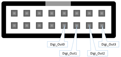
Output pin locations
The 4 output channels are located on the AUX port, at the back of the SmartScope.

Output voltage levels
As output voltage levels, you can select between 2 standards:
- 0V - 3V
- 0V - 5V
These voltages are selectable for an entire waveform and for all 4 channels together, not per sample nor per channel. In order to select the voltage, go to Menu -> Generator -> Digital -> Voltage level
Generating pre-defined waves
You can generate the predefined digital waves exactly the same way as desribed in Arbitrary Waveform Generator (AWG). Just make sure you have checked the checkbox in the Digital menu entry, to enable the digital output.
Define arbitrary waveforms in Excel (.csv file upload)
| Parameter | Range | Description |
|---|---|---|
| DataIsBytes | 0 or 1 | Indicates if the data should be interpreted as bytes (for the 4 digital outputs). If '0', it will be interpreted as voltages (for the analog output). |
| Samples | 1-2048 | The number of samples used. The AWG loops on these samples. (< 0.0.8.4 had a minimum of 128 samples) |
| SampleStretch | 0-255 | The number of cycles to repeat each sample. If 0, sample update rate is 100MHz. If n, sample update rate is 100/n MHz. |
| BeginData | Field to indicate that from here on the sample voltage levels follow |
Each row defines a sample as byte value, where the 4 LSB define the values of the 4 output pins.
| CsvValue | Output3 | Output2 | Output1 | Output0 |
|---|---|---|---|---|
| 0 | 0 | 0 | 0 | 0 |
| 1 | 0 | 0 | 0 | 1 |
| 2 | 0 | 0 | 1 | 0 |
| 3 | 0 | 0 | 1 | 1 |
| 4 | 0 | 1 | 0 | 0 |
| 5 | 0 | 1 | 0 | 1 |
| 6 | 0 | 1 | 1 | 0 |
| 7 | 0 | 1 | 1 | 1 |
| 8 | 1 | 0 | 0 | 0 |
| 9 | 1 | 0 | 0 | 1 |
| 10 | 1 | 0 | 1 | 0 |
| etc | etc | etc | etc | etc |
Sample digital output CSV
Value;Field;Description
1;DataIsBytes;Set to 1 to interpret the data as bytes, otherwise interpreted as voltages
8;Samples;The number of samples to use (later samples are ignored)
244;SampleStretch;The number of times to repeat a sample
0;BeginData;Data begins here
1;;
2;;
4;;
8;;
4;;
2;;
1;;