Controlling your SmartScope from LabView: Difference between revisions
mNo edit summary |
mNo edit summary |
||
| Line 1: | Line 1: | ||
LabView allows engineers to make responsive GUIs in hours, instead of weeks. Signal acquisition and generation devices can be bought from National Instruments, but they come at a cost. The SmartScope with its dual 100MS/s digitizers and 4MS of on-board RAM is an interesting alternative, and now comes with a set of VI blocks which allow you to configure and read out the SmartScope with ease. | LabView allows engineers to make responsive GUIs in hours, instead of weeks. Signal acquisition and generation devices can be bought from National Instruments, but they come at a cost. The SmartScope with its dual 100MS/s digitizers and 4MS of on-board RAM is an interesting alternative, and now comes with a set of VI blocks which allow you to configure and read out the SmartScope with ease. | ||
<p>This page explains all steps necessary to create the GUI shown below. Moreover, LabNation’s interface software is 100% open-source, and this page explains how to access more advanced features of this underlying library. | <p>This page explains all steps necessary to create the GUI shown below. Moreover, LabNation’s interface software is 100% open-source, and this page explains how to access more advanced features of this underlying library.<br> | ||
[[File:im1.png]] | [[File:im1.png]] | ||
<br><br>Behind this GUI is the block diagram shown below. Notice that the bottom part is only needed to update the GUI; all control and acquisition steps are done by the topmost part. All steps and VI blocks are be described below: | <br><br>Behind this GUI is the block diagram shown below. Notice that the bottom part is only needed to update the GUI; all control and acquisition steps are done by the topmost part. All steps and VI blocks are be described below: | ||
Latest revision as of 19:30, 19 June 2018
LabView allows engineers to make responsive GUIs in hours, instead of weeks. Signal acquisition and generation devices can be bought from National Instruments, but they come at a cost. The SmartScope with its dual 100MS/s digitizers and 4MS of on-board RAM is an interesting alternative, and now comes with a set of VI blocks which allow you to configure and read out the SmartScope with ease.
This page explains all steps necessary to create the GUI shown below. Moreover, LabNation’s interface software is 100% open-source, and this page explains how to access more advanced features of this underlying library.
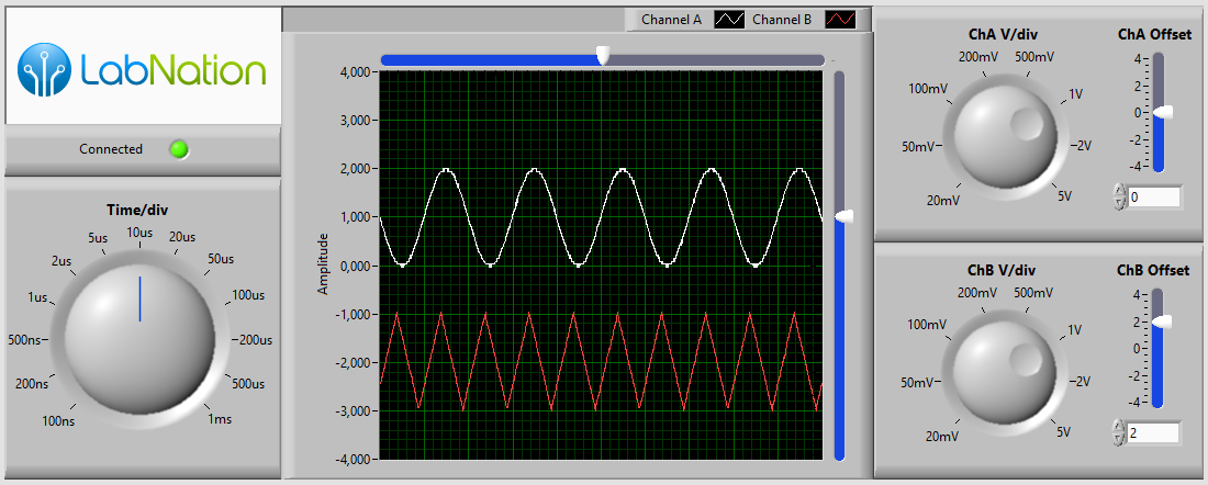
Behind this GUI is the block diagram shown below. Notice that the bottom part is only needed to update the GUI; all control and acquisition steps are done by the topmost part. All steps and VI blocks are be described below:
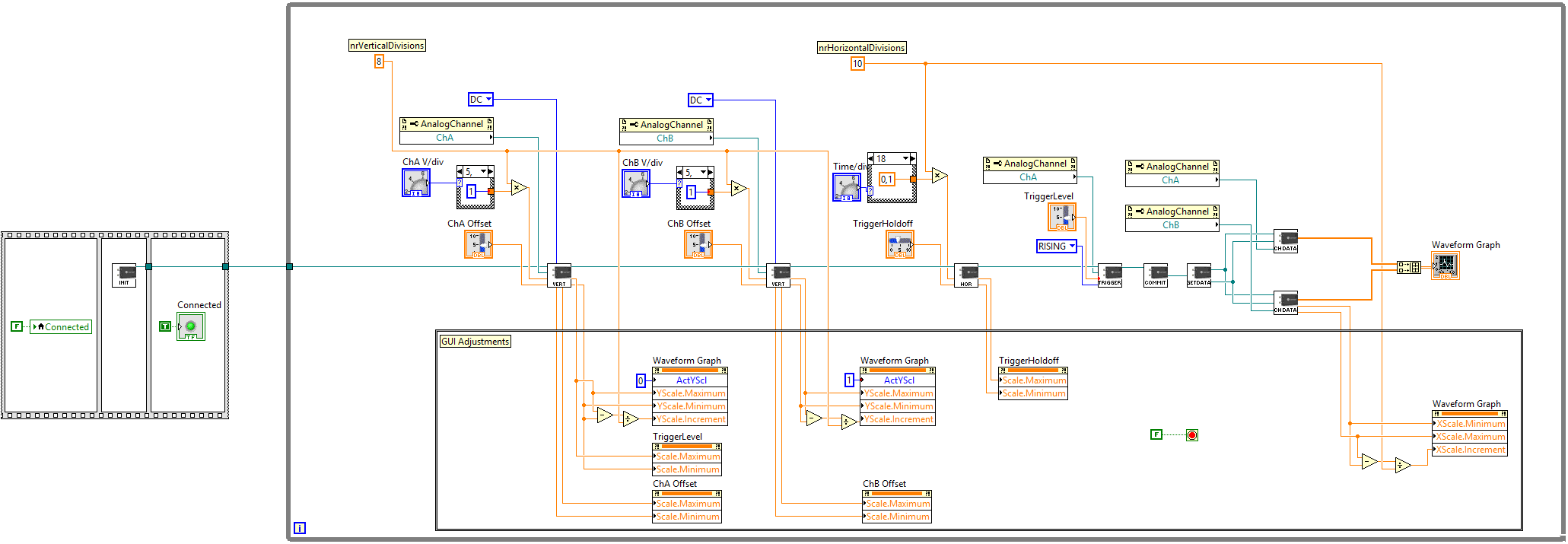
Downloading the SmartScope LabView VI's
Simply head to our LabView repo on GitHub and get those files on your PC. You can either clone the repo, or if you like it simple you can simply hit the 'Clone or Download' button and select Download .zip file. Extract these files to any location you want. The DemoGUI.vi is probably the file you'll want to try out first.
Using the SmartScope in a LabView application
When using the SmartScope in LabView, there are 3 phases to go through. This section lists them, together with all VIs for each phase.
Phase1: Initializing the SmartScope
This phase searches for a physical SmartScope, and returns a reference to the SmartScope which is needed by all other LabNation Vis.
INIT: Initialize.vi
When executed, this VI polls every 500ms whether a SmartScope is detected. This can be a SmartScope connected locally on the USB port, or a SmartScope shared over the network using the SmartScopeServer. Once detected, this VI will upload a basic configuration to the SmartScope and cause it to enter Running mode. The output of this VI is a reference to the SmartScope, and is needed for all other LabNation VI blocks. In practice, this means the dataflow in your block diagram will be blocked until a SmartScope becomes available.
Phase2: Configuring the Smartscope
At some point in your application, you will want to configure the acquisition settings of the SmartScope. This includes voltage ranges of the analog inputs, or the depth of the on-board RAM. It is important to note that all changes will only take effect after you’ve executed the CommitSettings.vi.
VERT: SetVertical.vi
This VI allows you to configure the analog input channels of the SmartScope. Below are the expected inputs:
- Voltage range: Simply pass it the largest amplitude you expect to measure, and the SmartScope will automatically change its dividing and multiplying stages in order to optimize its range for this amplitude.
Note that in order to get the finest resolution for your signal, it is best to set the voltage range as small as possible, while still making sure your entire signal can fit within that range.
- Offset: The value you specify here will be physically added or subtracted from the input voltage. This allows you to zoom in on a certain voltage range not centered around 0V. For example, if you want to measure signals between 0V and 12V, setting the voltage range to 12V and the offset to 6V will result in the highest measurement resolution.
- Coupling: This input terminal allows you to specify whether you want to have AC or DC coupling. DC coupling results in absolute voltages, while AC coupling first subtracts the mean value from the signal before being digitized. AC coupling allows to zoom in on signals with small amplitude but large offsets.
- Channel: last but not least, you should specify whether you’re configuring Channel A or Channel B.
HOR: SetHorizontal.vi
This VI is a simplified version which allows you to define very basic timing settings. If you want to have more control over the timing settings including on-board RAM, see the last section of this page. Here are the required inputs:
- ViewportLength: allows you to define the length of the sequence to acquire, in seconds, and adjusts the sampling rate so the Viewport buffer of 2048 samples correspond to this length.
- TriggerHoldoff: specifies the position of the trigger, in seconds, relative to the center of the Viewport.
TRIGGER: AnalogTrigger.vi
This VI allows you to configure a basic analog trigger, using the following inputs:
- Channel: Which analog channel you want to trigger on
- EdgeType: This VI only supports Rising, Falling or Any edge.
- TriggerLevel: The voltage, when being crossed, causing a trigger event to occur
COMMIT: CommitSettings.vi
An understanding of this VI is quite important. Any changes you make through the previous VIs will have no effect until the CommitSettings VI is called. Using the previously described VIs, all changes you make are made in shadow registers, which are copied in 1 shot to the real registers only when you call the CommitSettings VI. This ensures acquisitions are made with a complete configuration.
Phase3: Reading out SmartScope data
At any moment, you can fetch the latest datapackage from SmartScope. A datapackage is a coherent set of information, containing the acquired data for all channels as well as information regarding the configuration used during the acquisition. It is important to have all of this data in one package, to ensure all data from different channels was acquired at the same moment in time.
GETDATA: GetLatestDataPackage.vi
This VI simply fetches a reference to the latest datapackage received by the SmartScope driver. In case of acquisitions with a very long ViewportLength, it can happen that this VI is called multiple times during the same acquisition. In such case, the same reference to the last datapackage will be returned.
CHDATA: GetChannelData.vi
As explained above, a datapackage contains all data which was acquired at the same time for all channels. The GetChannelData VI simply returns the viewport data for the channel you specify, presented as a 1D array of floats. The Viewport data fetched by this VI are up to 2048 samples which span the duration you specified in the SetHorizontal VI. This VI requires a reference from the GetLatestDataPackage VI, as well as the analog channel you want to get the data from.
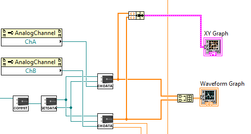
Adding a XY plot
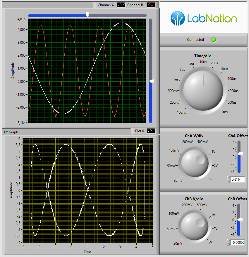
With the SmartScope data available to your LabView program, it is incredibly easy to add new representations fast. For example, adding a XY plot is simply a matter of wiring in LabView’s XY Chart VI:
Which allows you to re-arrange the GUI easily:
Accessing more advanced LabNation.DeviceInterface functionality
The software which interfaces with the SmartScope is 100% open-source. This DeviceInterface library is the only piece of code between your LabView environment and your SmartScope. As such, all functionality used by the official SmartScope app is accessible, also to LabView. Even though the VIs presented allows only basic operations, it is easy to use these more powerful features.
As an example, let’s set up a slightly more advanced pulse-width trigger. The trigger should only fire when a pulsewidth between 10us and 100us is detected. While this would not be possible using the VIs described above, the SmartScope supports this through the DeviceInterface, and hence we can use it from LabView. And it’s not all that difficult.
To start, open up the AnalogTrigger VI and copy-save it to AnalogTriggerPulse. Have a look at the block diagram:

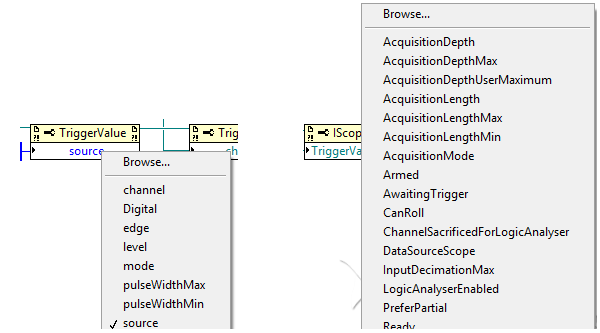
You see this diagram contains new blocks. LabView takes the DeviceInterface library, and automatically creates these blocks for all functions inside the library. To give you an idea, simply click on any Property of a TriggerValue block, eg on ‘source’. You will see a nice drop-down list of all properties you can set. Click also on the ‘TriggerValue’ Property of the IScope object on the bottom-right: you’ll get a list of all Properties of the SmartScope you can set. These are explained on the DeviceInterface section of the LabNation wiki, and 100% of the source can be found on LabNation’s GitHub account.
If we want to change the trigger from simple edge-detection to pulse detection, simply add the 3 blocks shown below. You can simply copy-paste the blocks above, and change their properties to ‘mode’, ‘pulseWidthMin’ and ‘pulseWidthMax’.
To create the ‘Pulse’ constant, simply right-click on the ‘mode’ terminal, select Create->Constant and LabView will automatically present you a list of the various possibilities. The other 2 constants define the minimum and maximum pulse width, which are now fixed but you can easily make them adjustable by using a Control instead of a Constant.

Voila, when you use this new subVI in your main VI, your SmartScope will reject all triggers which are shorter than 10us or longer than 100us.