Arbitrary Waveform Generator (AWG): Difference between revisions
JamesNewton (talk | contribs) |
No edit summary |
||
| Line 7: | Line 7: | ||
* The ground, so both devices have the same reference voltage. (0V means the same on both devices) | * The ground, so both devices have the same reference voltage. (0V means the same on both devices) | ||
In the image above, you can see the AWG pin is surrounded by 2 ground pins, either of which you can use to connect to the other device. | In the image above, you can see the AWG pin is surrounded by 2 ground pins, either of which you can use to connect to the other device. | ||
= How the AWG works = | |||
The AWG is driven by a 100MHz clock, reading out a memory containing *up to* 2048 samples. | |||
{| class="wikitable" | |||
|- | |||
! Parameter | |||
! Range | |||
! Description | |||
|- | |||
| Samples | |||
| 1-2048 | |||
| The number of samples used | |||
|- | |||
| SampleStretch | |||
| 0-255 | |||
| The number of cycles to repeat each sample | |||
|- | |||
| BeginData | |||
| | |||
| Field to indicate that from here on the sample data follows | |||
|} | |||
= Configuring the AWG using pre-defined waves = | = Configuring the AWG using pre-defined waves = | ||
= Configuring the AWG using csv files = | = Configuring the AWG using csv files = | ||
'''IMPORTANT''': The app expects the CSV file to use a semicolon (;) as a field separator and a comma (,) as decimal symbol. Download one of the samples below to make sure your CSV works. | |||
'''NOTE''': This only works with a SmartScope connected. Otherwise, the side menu won't contain an AWG item | '''NOTE''': This only works with a SmartScope connected. Otherwise, the side menu won't contain an AWG item | ||
If you haven't used dropbox with the SmartScope | If you haven't used dropbox with the SmartScope | ||
Revision as of 09:12, 2 March 2015
The SmartScope has an Arbitrary waveform generator, capable of generating signals between the [0V, 3.3V] voltage range at a sample rate of 100MS/s.
AWG pin location
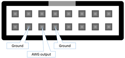
The signal generated by the AWG is presented on the 3rd-left pin on the bottom row of the AUX connector, as shown in the following image:

Please keep in mind that you always should bridge 2 wires between 2 separate devices. In this case:
- The AWG output signal
- The ground, so both devices have the same reference voltage. (0V means the same on both devices)
In the image above, you can see the AWG pin is surrounded by 2 ground pins, either of which you can use to connect to the other device.
How the AWG works
The AWG is driven by a 100MHz clock, reading out a memory containing *up to* 2048 samples.
| Parameter | Range | Description |
|---|---|---|
| Samples | 1-2048 | The number of samples used |
| SampleStretch | 0-255 | The number of cycles to repeat each sample |
| BeginData | Field to indicate that from here on the sample data follows |
Configuring the AWG using pre-defined waves
Configuring the AWG using csv files
IMPORTANT: The app expects the CSV file to use a semicolon (;) as a field separator and a comma (,) as decimal symbol. Download one of the samples below to make sure your CSV works.
NOTE: This only works with a SmartScope connected. Otherwise, the side menu won't contain an AWG item If you haven't used dropbox with the SmartScope
- Tap sidemenu > AWG > Upload from dropbox
- The app will tell you it doesn't have permission to dropbox and ask for it by sending you off to the dropbox website
- Grant access and return to the app
- The app now creates the AWG folder and will inform you that this new folder is empty.
- Generate a CSV file using the AWG excel worksheet. A sample CSV can be found for a sine and block wave.
- Drop your CSV file in the AWG folder (<dropbox>/Apps/LabNation SmartScope/AWG) using a file manager
- In the app, tap sidemenu > AWG > Upload from dropbox
- You should now be able to choose the CSV file