Changing the appearance of the app
The SmartScope software contains a couple of features which allow you to slightly tune its appearance to your liking.
Changing color mode
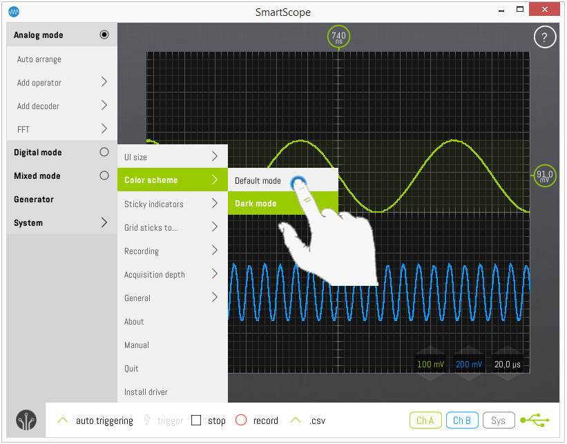
At this moment, the SmartScope software comes in two color schemes, the bright ‘Default’ mode and the ‘Dark’ mode. You can change between color mode at any moment during operation. To do so, go to Menu -> System -> Color scheme and pick the color mode of your choice.

Changing the size of the GUI elements
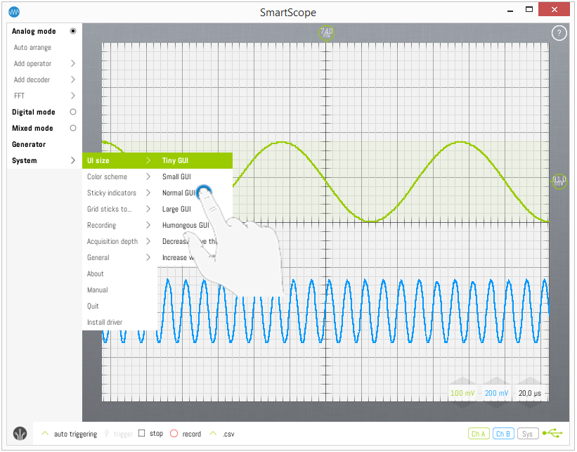
Determining the size of all interface elements is not so straightforward, because we need to support low resolutions on large PC monitors, as well as ultra-high resolutions on tiny smartphones. We have our algorithms, but in case you would prefer larger/small icons you can adjust your settings by 2 degrees (larger or smaller). Simply go to Menu -> System -> UI Size and try which one you prefer.

Waveform thickness
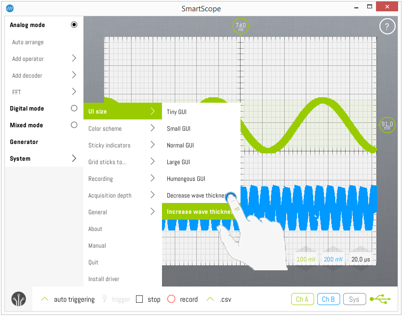
The default thickness in which your waves are rendered is determined automatically, but you can also set this manually. To do so, go to Menu -> System -> UI Size and select Decrease/Increase wave thickness:

Changing the colors of the waveforms
You can define the colors of the waveforms in the XML file which contains the settings.
Inside this .xml file, find either WaveColorsNormal or WaveColorsDark, and then find the waveform you want to change the colors of.
This is done by specifying the ABGR (Alpha,Blue,Green,Red) values between 0 and 255 directly. It is recommended to leave the A(alpha) value at 255.
The location of this .xml file can be found in the First aid kit.
Example:
Assume you would like to change the color of ChannelA in Dark mode, find this section in the file:
<WaveColorsDark xmlns:d2p1="http://schemas.microsoft.com/2003/10/Serialization/Arrays">
   <d2p1:KeyValueOfMappedColorColori_SCO11PS>
     <d2p1:Key>AnalogChannelA</d2p1:Key>
     <d2p1:Value xmlns:d4p1="http://schemas.datacontract.org/2004/07/Microsoft.Xna.Framework">
       <d4p1:A>255</d4p1:A>
       <d4p1:B>0</d4p1:B>
       <d4p1:G>204</d4p1:G>
       <d4p1:R>153</d4p1:R>
     </d2p1:Value>
Note the A,B,G and R values are set to 255,0,204,153 by default respectively. You can disregard the A(lpha) value, as it simply means the color is opaque (non-transparent).
Next, you find any RGB color picker (first google result: https://www.rapidtables.com/web/color/RGB_Color.html), pick the color of your choice, find the corresponding RGB values, and replace the values in the XML file with those from the color picker.
As an example, to obtain a Cyan wave you would change to 0 Red, 255 Green, 255 Blue:
<WaveColorsDark xmlns:d2p1="http://schemas.microsoft.com/2003/10/Serialization/Arrays">
   <d2p1:KeyValueOfMappedColorColori_SCO11PS>
     <d2p1:Key>AnalogChannelA</d2p1:Key>
     <d2p1:Value xmlns:d4p1="http://schemas.datacontract.org/2004/07/Microsoft.Xna.Framework">
       <d4p1:A>255</d4p1:A>
       <d4p1:B>255</d4p1:B>
       <d4p1:G>255</d4p1:G>
       <d4p1:R>0</d4p1:R>
     </d2p1:Value>