Calibrating the probes
(copied from the original forum post by Thoralt back in 2014, updated to the latest GUI)
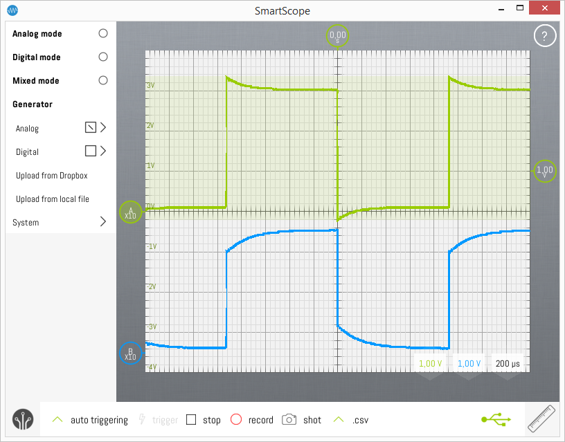
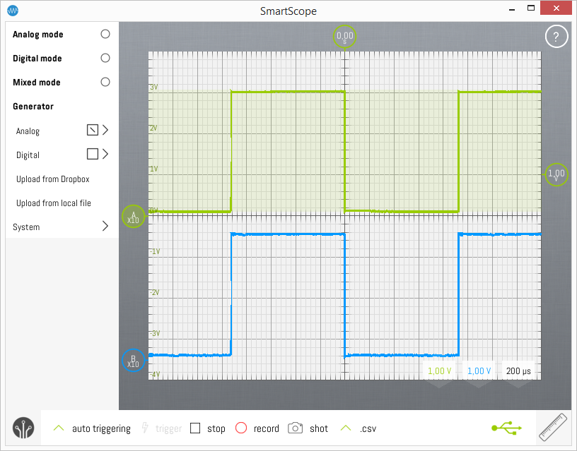
Most makers might already know what I'm talking about, but since the SmartScope is likely to be used by electronics newbies, too, I want describe the probe calibration process. To see why this is needed, check both images below, where a square wave is being probed. The probes delivered with the SmartScope have a defined impedance which needs to be matched against the input impedance of the scope to get a flat frequency response (at least up to the maximum input frequency of the scope). Doing this is an easy process: Switch both of the probes to 10x mode and connect them to the AWG output. (see Connectors pinout)
Set the AWG to a square wave of approx. 500 Hz. To do this, follow these steps:
- In the main menu, select Generator
- Make sure you check the box next to its submenu Analog (to enable the AWG)
- Click Analog to expand the options
- For Shape, select Square
- Drag the frequency to any value between 500Hz and 1kHz
- Leave the amplitude to 3V and offset to 100mV
- Click Upload
Next, scale both waveforms to 1V/div and 500 us/div (drag the selectors at the bottom-right of the screen) to get a good overview of the waveforms. You might want to drag the trigger at the right side to stabilize the waveform. The following image shows a waveform in case the impedance is their worst state, one channel over compensated, the other under compensated:

Now use the little screwdriver tool provided with the probes to slowly turn the little screw inside the BNC connector of the probes until the waveform on the screen is as square as possible. If both channels look as shown below, you're done.
