Arbitrary Waveform Generator (AWG): Difference between revisions
Jump to navigation
Jump to search
(Created page with "The SmartScope has an Arbitraty waveform generator, capable of generating signals between the [0V, 3.3V] voltage range at a sample rate of 100MS/s. = AWG pin location = The si...") |
No edit summary |
||
| Line 9: | Line 9: | ||
= Configuring the AWG using pre-defined waves = | = Configuring the AWG using pre-defined waves = | ||
= Configuring the AWG using csv files = | = Configuring the AWG using csv files = | ||
This feature is still under development. Mobile users will be able to access their csv files through DropBox. | |||
Revision as of 16:30, 7 December 2014
The SmartScope has an Arbitraty waveform generator, capable of generating signals between the [0V, 3.3V] voltage range at a sample rate of 100MS/s.
AWG pin location
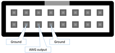
The signal generated by the AWG is presented on the 3rd-left pin on the bottom row of the AUX connector, as shown in the following image:

Please keep in mind that you always should bridge 2 wires between 2 separate devices. In this case:
- The AWG output signal
- The ground, so both devices have the same reference voltage. (0V means the same on both devices)
In the image above, you can see the AWG pin is surrounded by 2 ground pins, either of which you can use to connect to the other device.
Configuring the AWG using pre-defined waves
Configuring the AWG using csv files
This feature is still under development. Mobile users will be able to access their csv files through DropBox.