Using the Protocol Decoders
(You can use Protocol Decoders on both the Analog Graph and/or the Logic Analyzer Graph)
While examining the digital communication between 2 chips, did you ever find yourself counting rising edges and writing down 0’s and 1’s? This is where protocol decoders can save you a LOT of time.
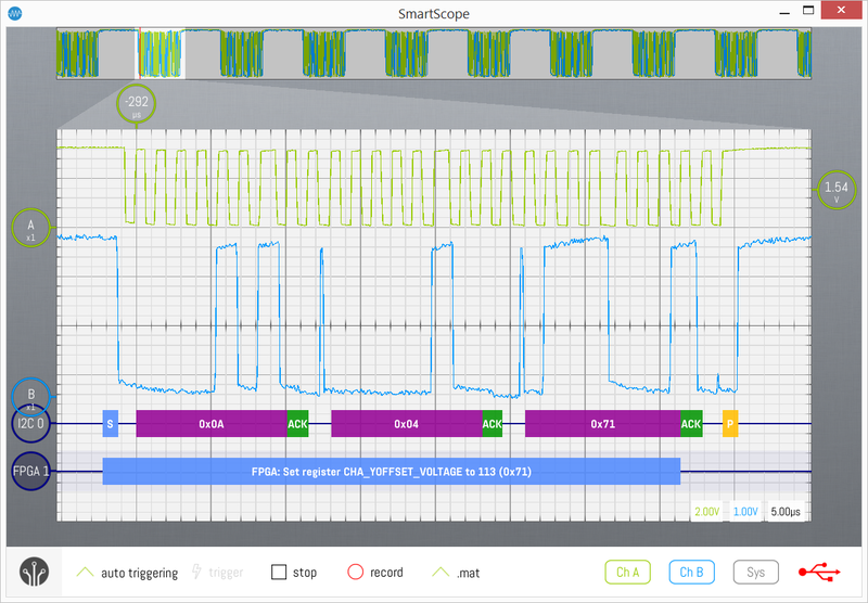
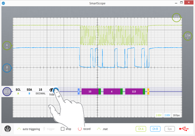
Not only do they convert rising edges into digital data for you; if you select the proper decoder, it will also separate messages and present you byte values. This means you can eg convert a clock and data waveform into I2C byte values, as shown in purple in the image below.
If you want to go one step further, you can even feed these bytes into your own decoder in order to translate them into humanly readable words specific to your application! See the screenshot below, where the output of the I2C decoder is converted into higher-level messages by a custom decoder, as shown in the blue blocks below.
Throwing in a decoder
Whenever you feel the need to have a decoder do the bitpicking for you, start by making sure you have the required input signals nicely aligned on your screen. This means you need to make sure the entire communication is visible. - While running, the entire communication should be visible in the Viewport (=main graph) - Preferrably, you'll catch the acquisition using 'Single trigger' mode, as this will allow the SmartScope to fetch the entire acquisition from onboard RAM into the Panorama of the visualizer. Once this has been done, you can get a much more accurate decoding, and you can zoom in to specific portions of interest within a larger communication.
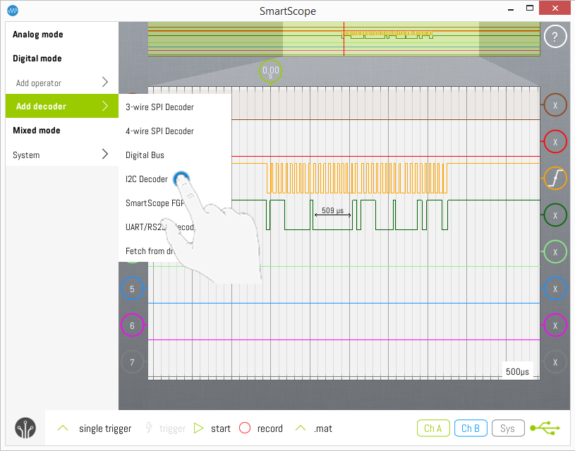
When done, simply slide open the main menu and hit Add decoder, which will bring up a list of currently available decoder. (Keep in mind you can easily create your own decoders, see [Creating your own decoder]). Select the decoder you would like to add, as shown in the image below where an I2C decoder is being added.
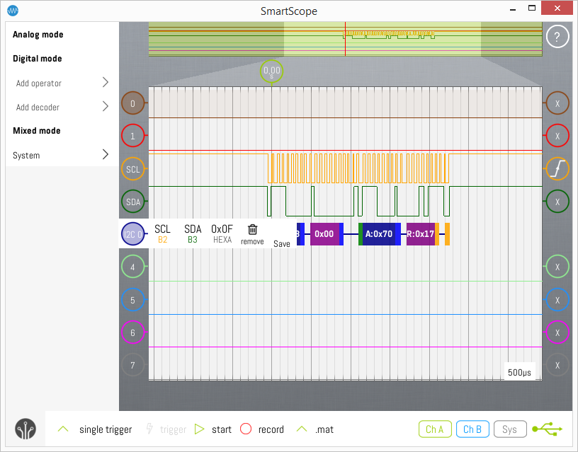
The decoder wave will be added to the main graph, and it context menu will be opened to give you a quick view on its settings (shown in the image below). The SmartScope software contains a feature which will try to automatically map the available input waves to the currect input of the decoder. Finally, just slide it vertically to where you like it to reside.
Configuring the decoder
All decoders require input waveforms, usually multiple of them. The SmartScope software contains a feature which will try to automatically map the available input waves to the currect input of the decoder. However, in some cases you might want to manually configure the input waves, or other parameters. In this step, you’ll let your decoder know which waves to use as which input.
As with all GUI elements of the SmartScope, if you want to configure the decoder, simply tap on the decoder. Its context menu will pop up, showing all configurable options (see image above).
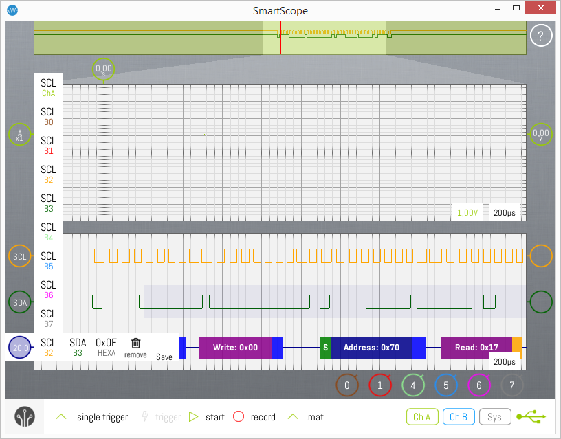
The first entries define which waves are linked to which input. In this specific case of an I2C decoder, there are 2 required inputs: the clock channel SCL and data channel SDA. In case you want to change which wave is being used as input, simply tap on that input, and a list of valid input candidates is shown. In the example below, SCL is tapped, bringing up a list of all possible input wave candidates. For digital inputs, such as SCL in our case, you can choose from all digital and analog waves. This is the reason why the following images was made in Mixed Mode: notice that you can use ChannelA as possible input channel for SCL, even though your I2C Decoder is on your digital graph.
Whenever you change an input channel of a decoder, the decoder will re-process any data immediately, also when the acquisition has been stopped. This allows you to acquire a dataset, and get immediately feedback while fine-tuning your decoder settings.
Changing the radix of the decoder
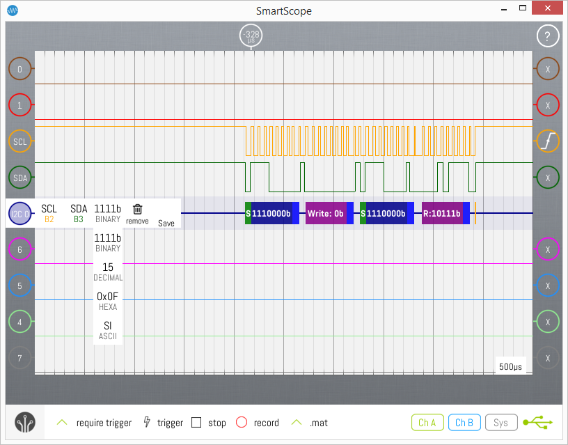
By default, decoder output values are shown in hexadecimal. Since not all of us are robots, it might be desirable to change this to decimal values or even other representations. In order to do so, simply tap the decoder indicator on the left, select the radix icon (second to the right), and select the radix of your preference! Currently supported radices include Hex, Decimal, Binary (shown below) and ASCII which will convert the byte value into its ASCII character.
Removing a decoder
If you want to switch back to manual bitpicking, simply tap the decoder indicator on the left, and select the thrashcan.
Decoding while running or when stopped
While the acquisition is running, the decoding is happening on-the-fly on the data is it is coming in. However, in this mode the decoders only have access to the data shown on the screen. Basically, if you cannot see all edges separately in the Viewport (the main graph), you cannot expect the decoders to decode on-the-fly.
Therefore, if you're not zoomed in enough, correct decoding will not be possible. If this is the case, you can stop the acquisition, after which each and every sample inside the RAM will be transfered to the software, allowing the decoders to do their processing in fine detail.
Save all decoded data to file
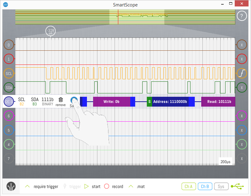
Visualizing the decoded data is nice, but in some cases you're really interested in the decoded data itself. To do so, open up the Context menu of the Decoder and tap the right-most icon 'Save'. This will store all decoded data in CSV format, including the start- and stop sample of each block, the type of each block and its value.
Create a custom Protocol decoder
See the Custom Protocol Decoder article.
